
Background
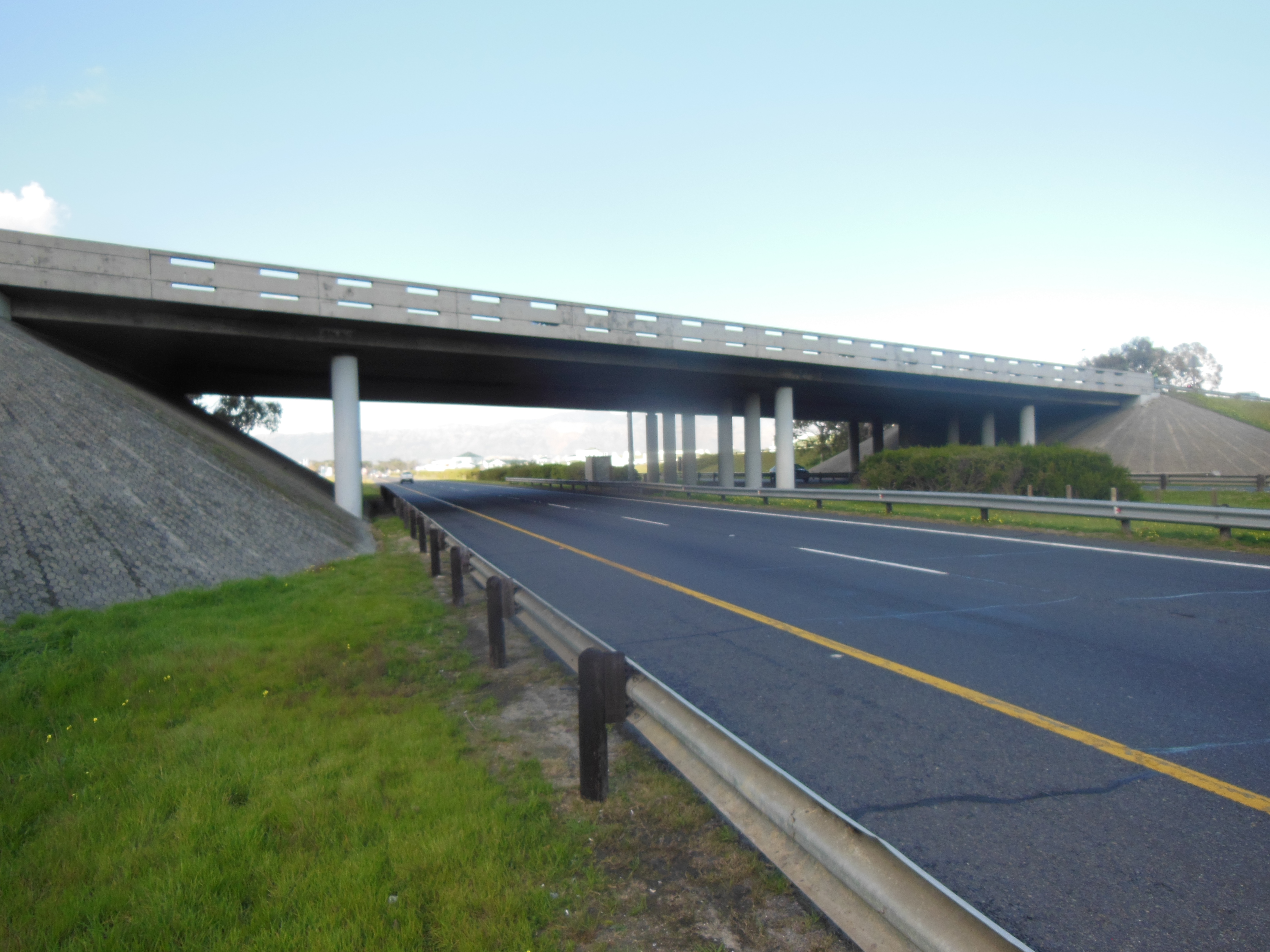
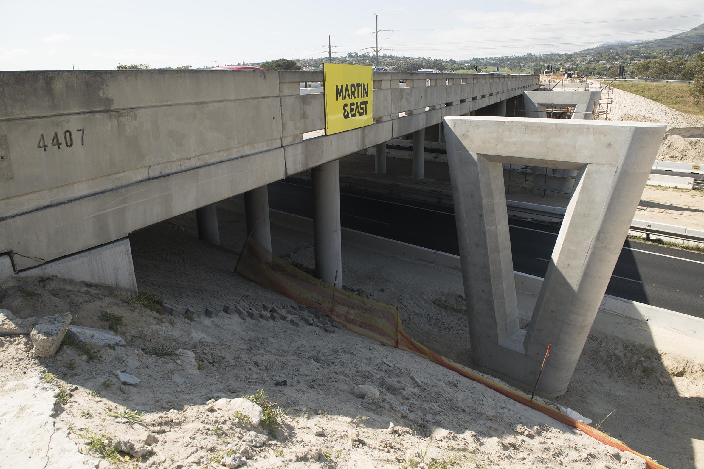
De Beers Interchange (Bridge B4407) was originally constructed in 1970 over the N2 national route to the west of Somerset West, in Western Cape, South Africa. The bridge was designed as a four-span 70 m long continuously post tensioned deck, to carry the R44 route over the N2. The superstructure rests on elastomeric bearings at the piers and abutments. The piers are 900mm diameter reinforced concrete columns founded on pad footings. The abutments are spill through type walls with stone pitching. The structure was in good condition, however required widening to allow for an additional traffic lane along the R44 as part of an upgrade cofunded by the City of Cape Town and the South African National Roads Agency Limited.
Preliminary Design
As built information was provided, which allowed designers to determine the load capacity of the existing structure. As the structure was constructed in 1970, it was assumed that the original design had adopted the BS 153 (1954) loading system in its structural analysis, which called for a uniformly distributed linear traffic load of 2200 pounds per foot to be applied, along with a single heavy axle line load of 2700 pounds per foot. By comparison, current loading requirements prescribed by TMH7 Part 1 and 2 have requirements of up to 20 – 60% higher than the BS 153 loading code. Despite this, the existing structure was assessed using SOFiSTiK finite element analysis software, and was deemed to comply with the TMH7:1981.
Widening Options
The existing structure had sufficient capacity to comply with TMH7:1981, however further widenings of the deck would impose additional dead loadings that the structure would not be able to accommodate. Widening options are compared below.
The initial proposal was a simple widening strategy that involved adding a light weight steel sidewalk at the farthest edge of the deck to accommodate pedestrians, and thus allowing for the reconfiguration of the road layout on the deck. This proposal added too much dead weight to the existing structure and was not pursued.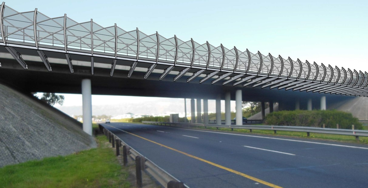
The revised proposal involved building a new structural steel pedestrian bridge directly adjacent to the existing deck on both sides to accommodate pedestrians. This ensured that pedestrian may cross the bridge safely, while still allowing for a reconfiguration of the road over the deck. The structure would form an exo-skeleton which incorporated s full height screen. This proposal was discarded due to potentially high maintenance costs due to the proximity of the site to the ocean.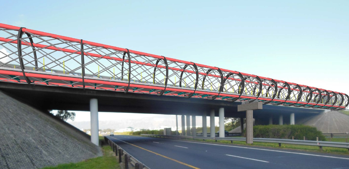
The proposed new pedestrian bridge option was revised to reduce the maintenance requirement over the life span of the structure. The resulting structure was a pretensioned concrete structure, built up of precast super structure elements, placed on an insitu substructure. The structure was also designed with a unique side profile to be visually appealing to the vehicle user below.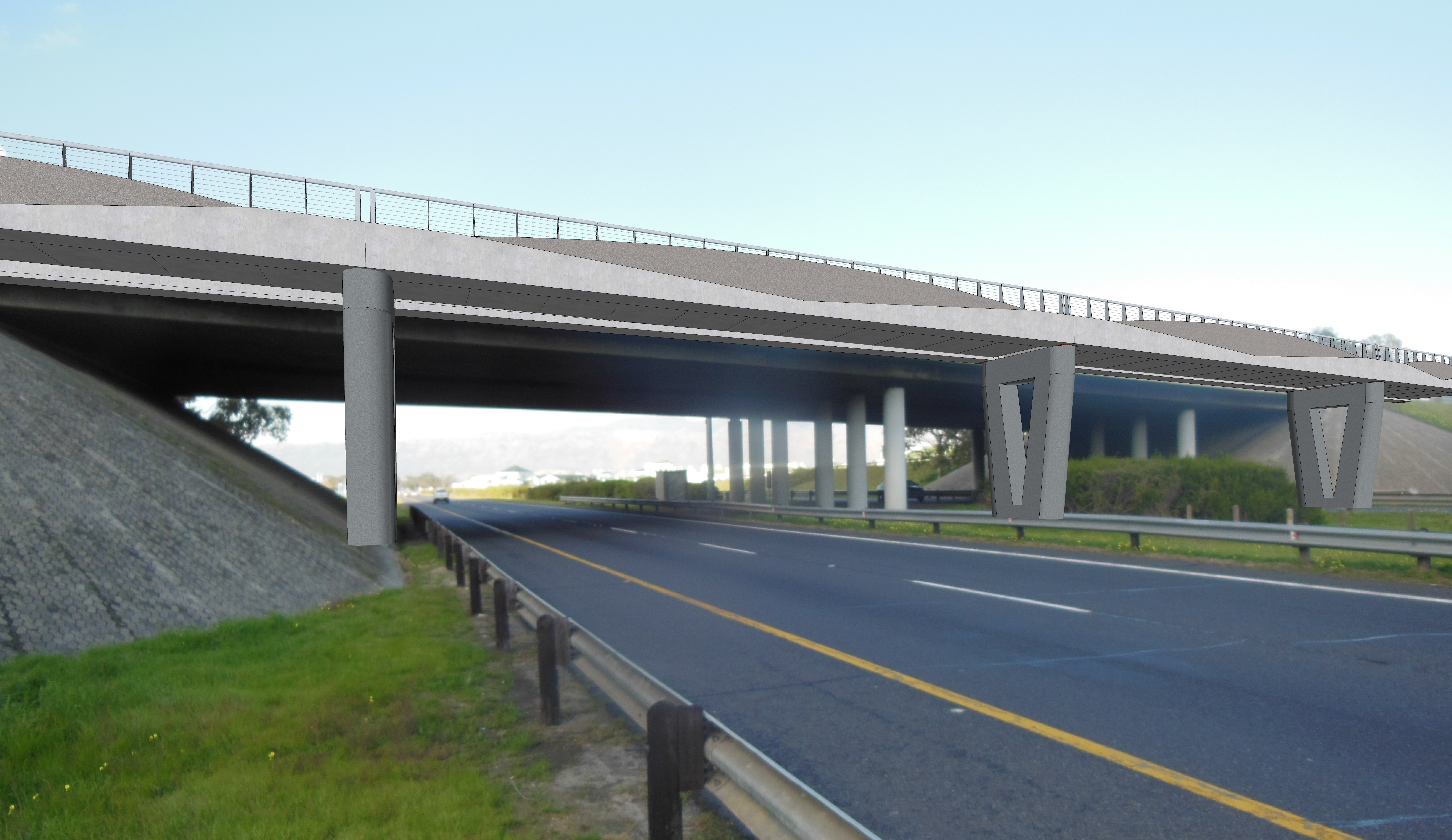
Column impact loading
Due to recent impact damage experienced by similar pedestrian structures, it was decided to increase the vehicle impact loadings that the piers would be required to accommodate. The resulting design is for triple the nominal forces required in TMH7.
Precast Beam Design & Sequencing
The superstructure is built up of 3 components, the precast beams, precast slabs and in-situ stitching. The beams are designed to maximize their bending moment capacity at the mid span, while also maximizing the shear capacity at the supports. The beams therefore had a variable cross section over its length, which had to be considered with the design software. Using SOFiSTiK, the beam was modelled using a parametric function which added a vertical curve to vary the cross section over its length. The results of the design were compared with the results of design checked through several spread sheets and hand calculation techniques. The result is a visually appealing, while also structurally robust beam element.
Construction
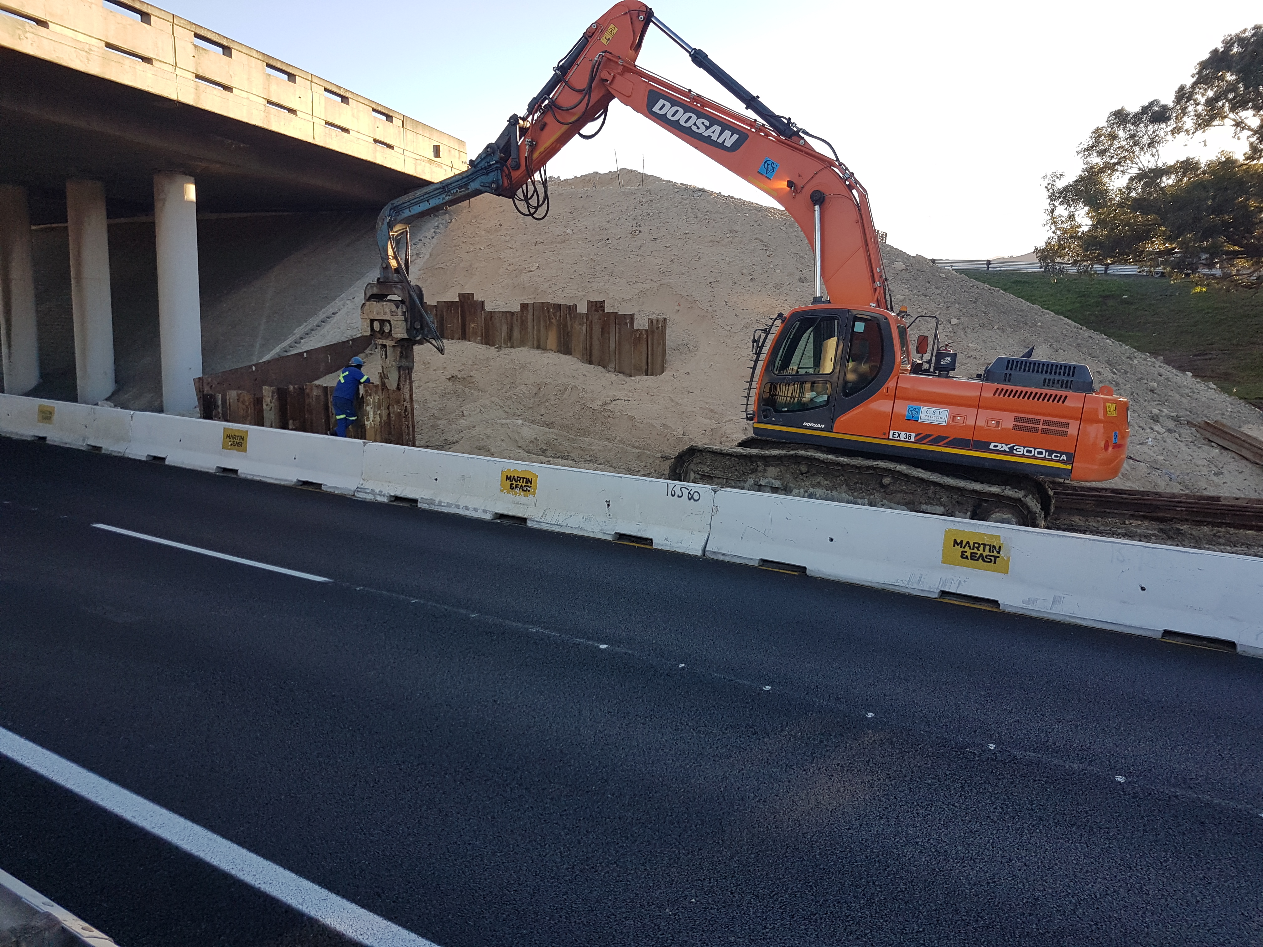
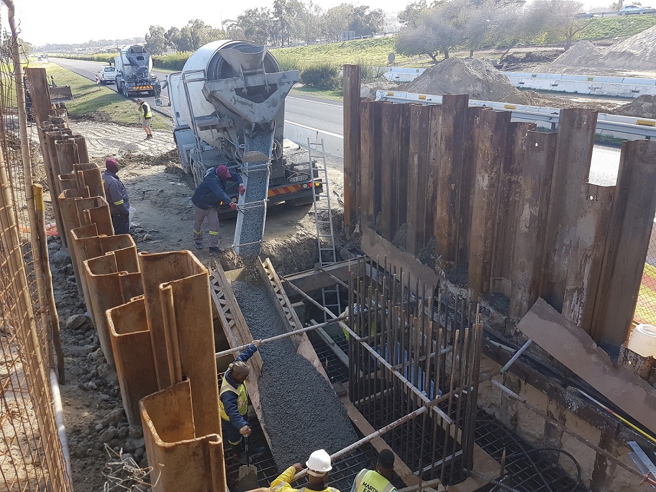
Foundation Conditions
Due to limited space available in the road reserve, and the positioning of the pier foundations being in close proximity to the edge of the N2 roadway and existing embankments, it was required to utilise sheet piling to preserve the layerworks and integrity of the embankment.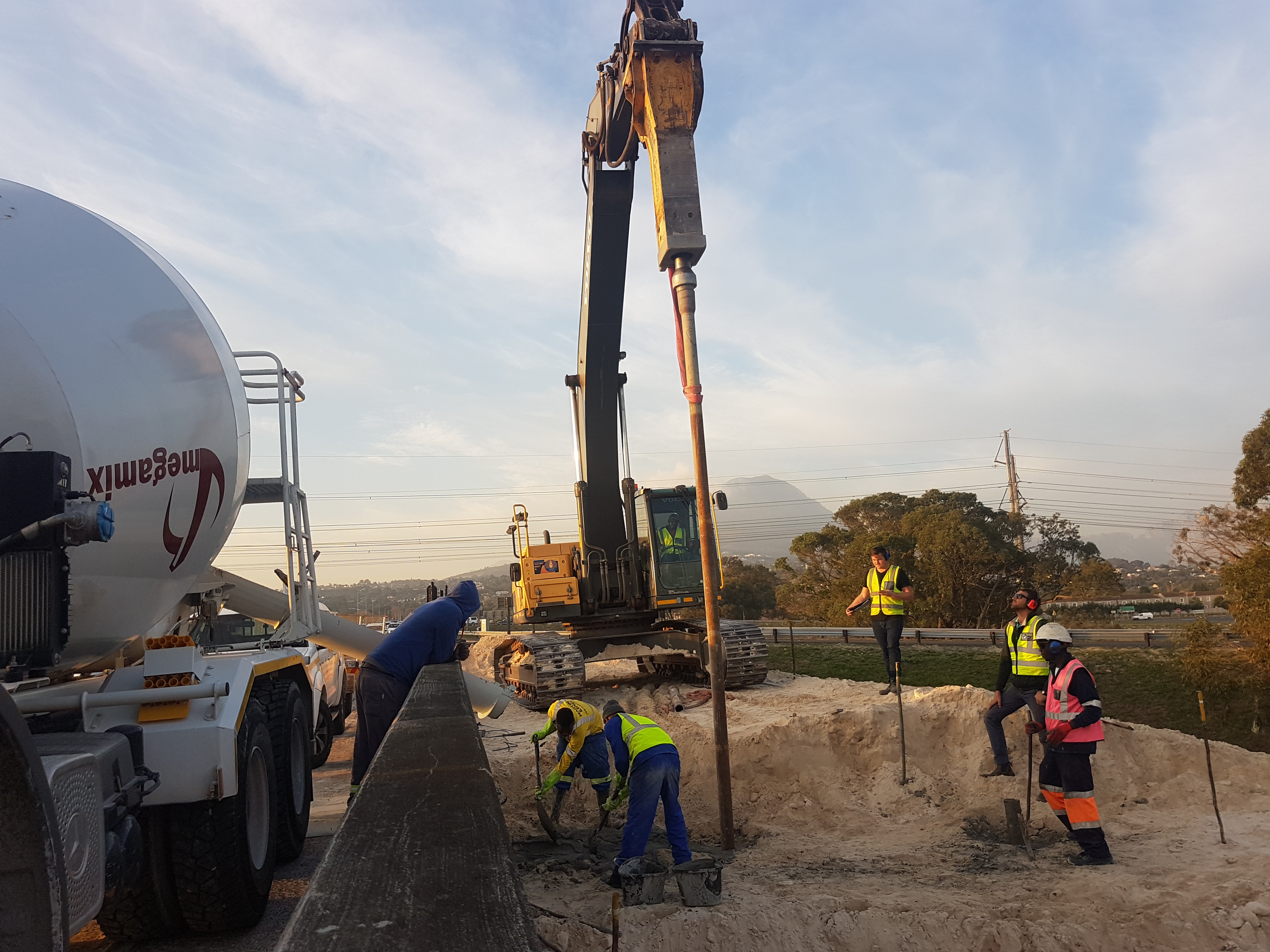
The beams and slab elements were manufactured offsite at the Cape Concrete yard to very strict tolerances, and brought to site prior to launching.
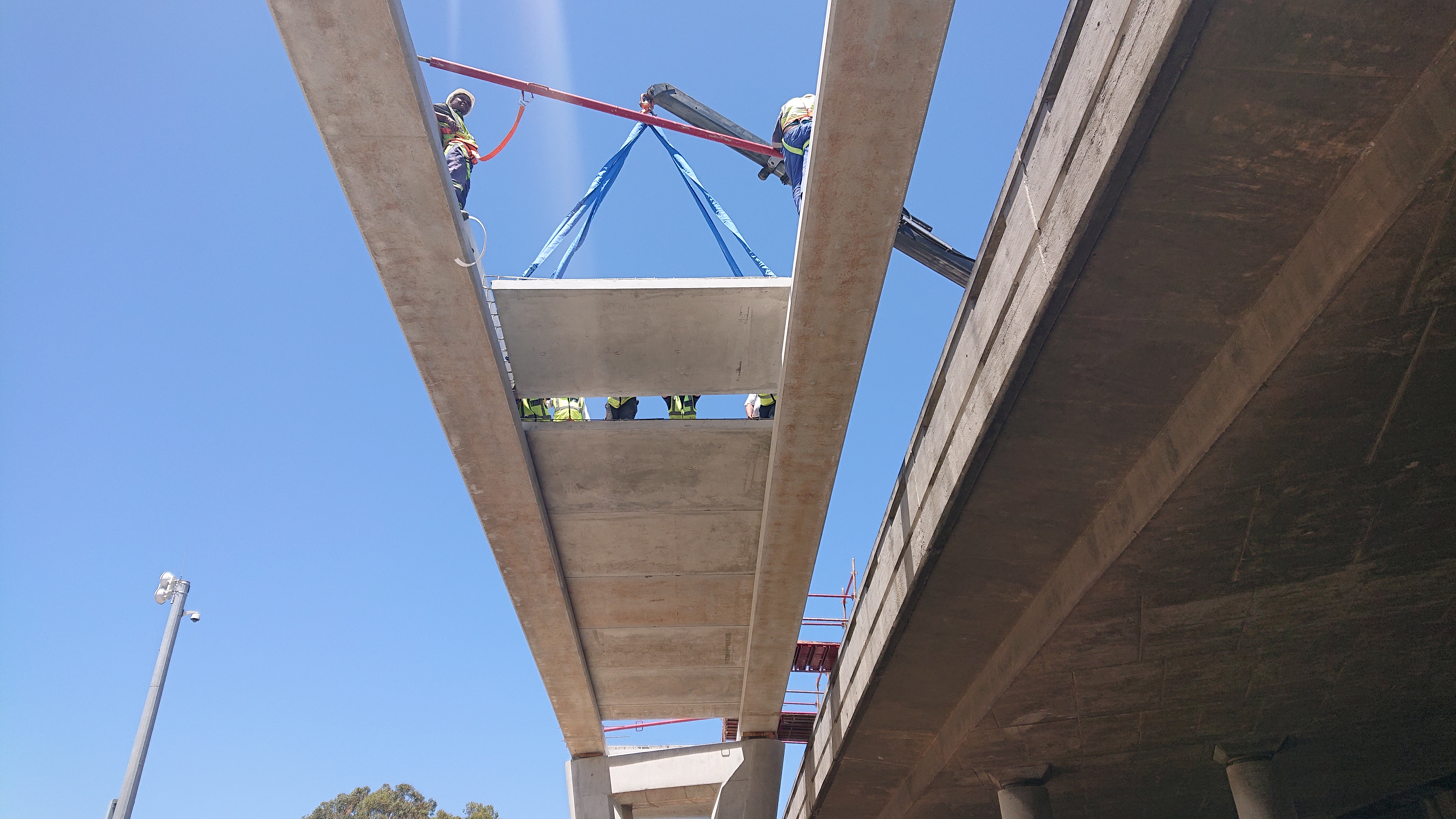
Beam Launching
Part of the N2 highway at Broadway boulevard bridge had to be closed in order to place the precast beams. The contractor was allowed a 19- hour window period over a weekend to launch the 12 precast beams, this resulted in 2 night launches of 10 and 9 hours each, for Saturday and Sunday night respectively. This accounted for the time required to transport the beams from the concrete yard, and the re- positioning of the Crane Truck on either side of the bridge. The inbound carriageway was closed on the Saturday night, and the outbound carriageway the Sunday night, and all the beams were successfully placed within the stipulated hours.
Traffic accommodation
To minimise traffic congestion due to the closure of the N2, traffic was directed to detours through intersections at Victoria Road / N2 intersection, Macassar Road Exit Ramp / N2, and through the Broadway Boulevard (R44) / N2 interchange via the exit ramps back onto the N2. This was achieved with careful interaction between the construction team and local traffic control authorities.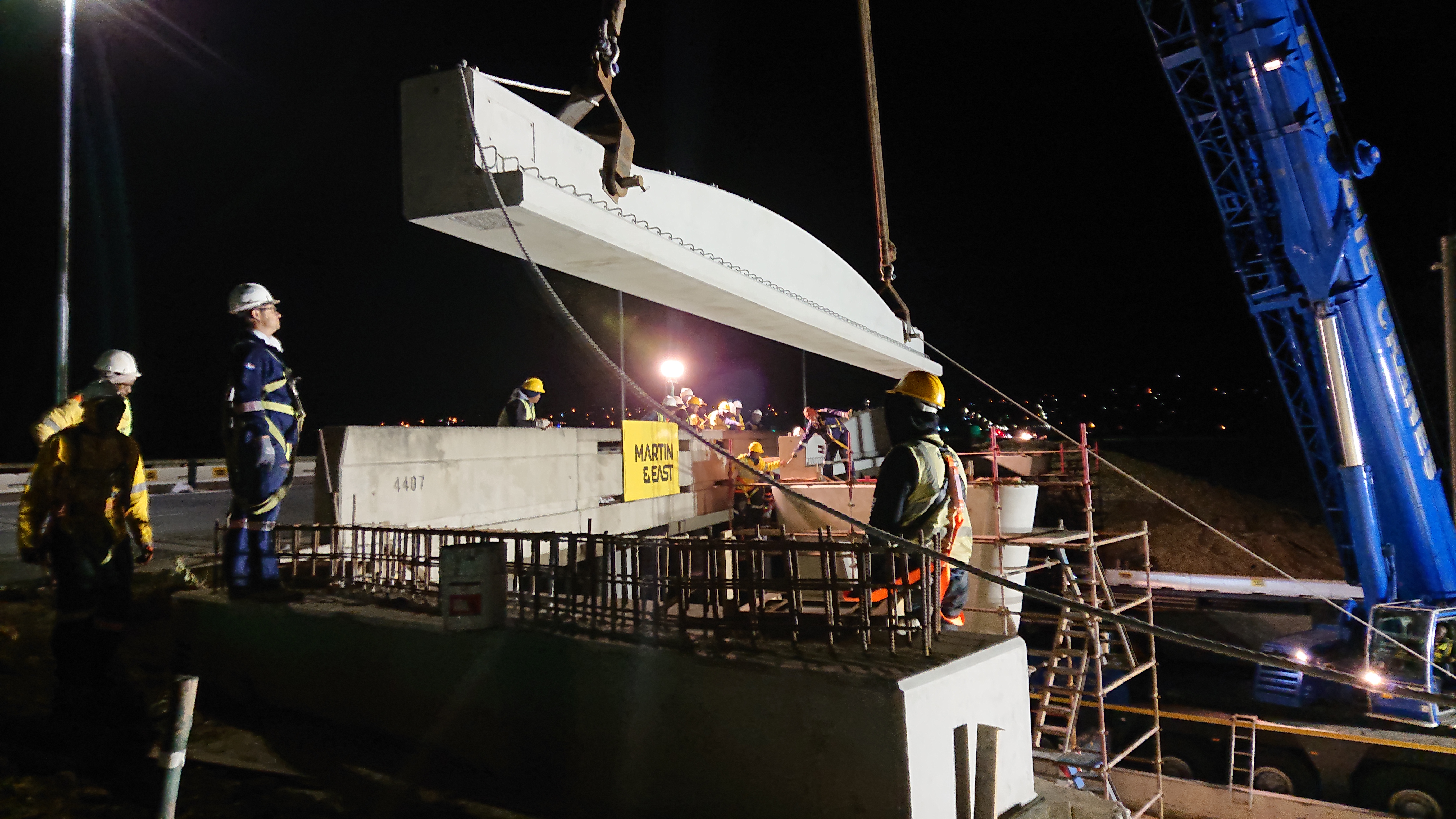
Click here to view the SAICE magazine extract